Minimum Headroom
Adapting a 32-pin EPROM such as the 27C010 for use in a 28-pin socket is a solved problem.[1] Whatever form that adaptation takes, whether it be jumpers soldered directly to the pins, piggybacked sockets, or a custom PCB, it's the same basic steps.
- Those pins which set the EPROM into READ mode are switched to whatever logic level the datasheet specifies, i.e., they are tied to
VCCorVSS. - Any address lines/pins on the EPROM which do not match those on the socket must be rerouted.
And in the case of a system/board which already expects ROMs with capacities less than or equal to 128KB, that's just about the extent of it.
However, the usage of such an adapted 27C010 in a TGC (TEMPEST GRiDCase)[2] presents a different challenge.
A TGC is cased in the same form factor as a standard model, but with reduced interior space, owing to the substantial number of modifications necessary to meet the TEMPEST EMI filtration/shielding requirements. These extensive modifications include hermetically sealed MIL-F-15733-specced power line filters, triple-leaded EMI suppression capacitors, and most notably, a two-part Faraday cage slash exoskeleton surrounding the entire motherboard. Boy, this cage has led to some particularly frustrating troubleshooting[3].
This will be an attempt to create an adapter which both uses the larger capacity 27C010 EPROM, and also fits inside the TGC's case without removing or modifying any of the TEMPEST-required additions.
A Bunch of Numbers

The daughterboard containing the ROM sockets is housed within a compartment on the surface of the shielded enclosure and connects to the motherboard by way of two 20-position vertical receptacles on its bottom side. These connectors, which extend past the rim of the compartment and into the enclosure itself, align with a matching set of headers on the motherboard below. Clip-on fingerstock gaskets run lengthwise across the top and bottom of the compartment and secure its cover -- after the application of a not insubstantial amount of "closure force"
The ROM compartment's interior height, with cover in place, is the absolute limit which the final height of an adapted EPROM + carrier must not exceed.
The cover is 0.018 inch-thick sheet metal[4] with an exterior height of 0.321 in. It slides into the ROM compartment, enshrouding the ROM board, itself 0.065 inch-thick. The cover's walls clear the edges of the board's outline and rest level on the base of the compartment.

The available vertical space is therefore the difference between the cover's overall height, 0.321 in., and the combined thicknesses of the cover and board, 0.083 in., which is 0.238 in.
A "stock" 28-pin EPROM, like the HN27512, is about 0.160 in. tall and when socketed on the board has an effective height of 0.215 in. This height then is presumably that which the ROM compartment's cover was expected to clear when fully inserted.
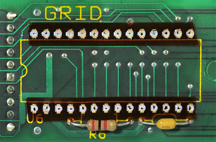
In addition to the height constraints, the layout of the ROM board also influences the possible footprint of any adapter. All four of the sockets share the same auxiliary component configuration: a 0.1 µF axial-leaded decoupling capacitor and a 2k Ohm pull-up resistor for pin 1 (A15/VPP). But, for each of the four sockets, there is one of three possible arrangements of those components.
Only one of these arrangements has components placed both above and below the rows of contacts. Consequently, its tolerances for an adapter board (which would need to come as close as possible to surface of the daughterboard) would be the tightest. Another has the capacitor and resistor stacked above, while the remaining two sockets have them running across the bottom row. Considering there's at least two of them, it seems reasonable to design for the latter arrangement.
With those horizontal constraints, it should just be a matter of keeping the adapter's bottom row of pads close enough to the board's edge to clear the components.
This leaves the 0.023 in. of vertical clearance as the significant challenge. Any additional hardware, such as a PCB in which to seat a 27C010, must not add more than 0.023 in. to the overall height. And, considering that the standard height of most prototyping services PCB is about 0.063 in., it's going to be a tight fit.
Given that manufacturers released pin-compatible EPROMs, such as the HN27301 or MBM27C1000, perhaps the easiest solution would be to buy the correct EPROM for the job? ↩︎
I'm taking that from their PCB. It did take a while for it to dawn on me what "TGC" stood for, I'll admit. ↩︎
I'm looking at you, screw hole directly over a metal-body crystal. ↩︎
Plated steel or copper alloy, I'm guessing? ↩︎