Sparing Expenses
The Battery Backplane

Initial AC-DC conversion, i.e., mains stepped down to 16V, occurs before power enters the system. This is performed in either GRiD's own AC Power Pack or a third-party converter, AKA a "wall-wart"
If one does use the power pack, DC enters at the terminals located on the rear-facing side of the battery backplane. Otherwise, power enters at the DC inlet below the power switch and runs to the connector near the CORCOM filter.
Once DC is provided, it's routed through the backplane to the DC-DC converter which lives between the I/O backplane and the Faraday cage surrounding the motherboard. After the different voltages required have been regulated and isolated, the lines return through the battery board and on to the motherboard's power entry module.
The TGC's power rails are:
| +5V | +12V |
| +15V | -15V |
| +5V | +3.6V |
| Vcc | Vss |
DC-DC
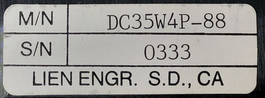
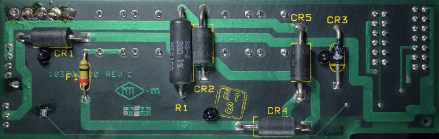
The DC-DC converter comes from Lien Engineering, a San Diego outfit which produced converters for multiple GRiDCase models.[1] Their units can be found in computers produced for the consumer market, such as the GRiDCase 2, 3, and Plus, as well as the later 15XX series.
Aside from Lien's own varying model numbers and the individual voltages regulated, I have not found any substantial differences, either in build quality, construction techniques, or component choice, between boards manufactured for the TGC and those for other GRiDCase models.
There is a daughterboard attached with right-angle header pins. The whole thing is housed in a three-quarters metal shell with brass spacers at each drill hole which I would guess are part of the design's heat dissipation strategy.
Regulating the DC-DC converter's temperature by exposing much of its surface area also makes it that much more vulnerable to environmental hazards like moisture and wildlife. A fortunate side effect of encapsulating the motherboard within a Faraday cage is that it is protected from these hazards.
Unfortunately, the subsystems situated outside the Faraday cage, and therefore exposed to the elements, (through the rather large ingress points presented by the battery cavity), are likely to bear the brunt of long-term storage's adverse effects. Unless the TGC's port is blocked by the presence of a battery or power pack.
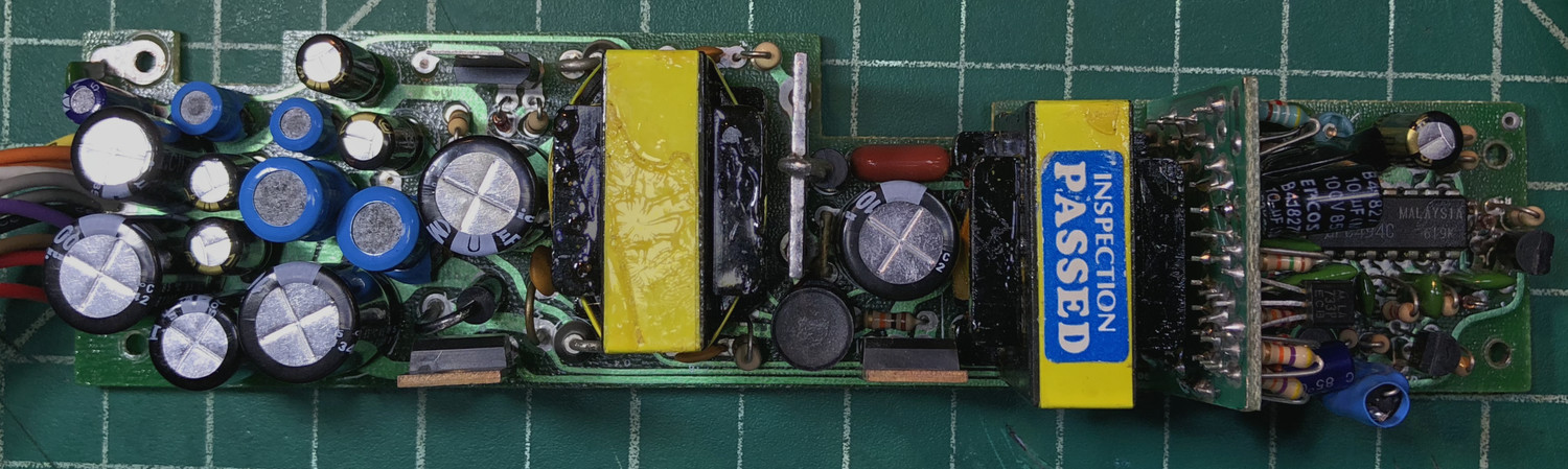
On one example, I replaced the MOSFET's because the short wires Lien soldered to each lead (I'm assuming to make it easier to line up the hole in the shell with the TO-220 packages) had disintegrated off the board. I would be willing to bet that this was a result of the storage environment; the soldermask was also peeling away in large chunks.
This is not to say that the Lien boards (like other switching power supplies) wouldn't fail for more prosaic reasons such as faulty electrolytic capacitors.
In fact, one board was magically brought back to life when I gave up troubleshooting and simply replaced every electrolytic capacitor I could find.
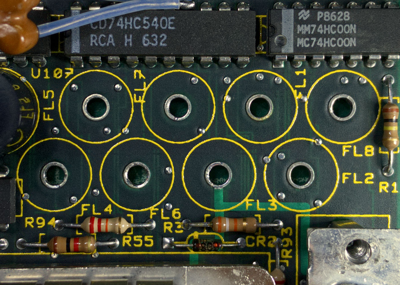
Power-Entry Module

The power-entry module is one of the seven openings on the TGC motherboard's shielding.
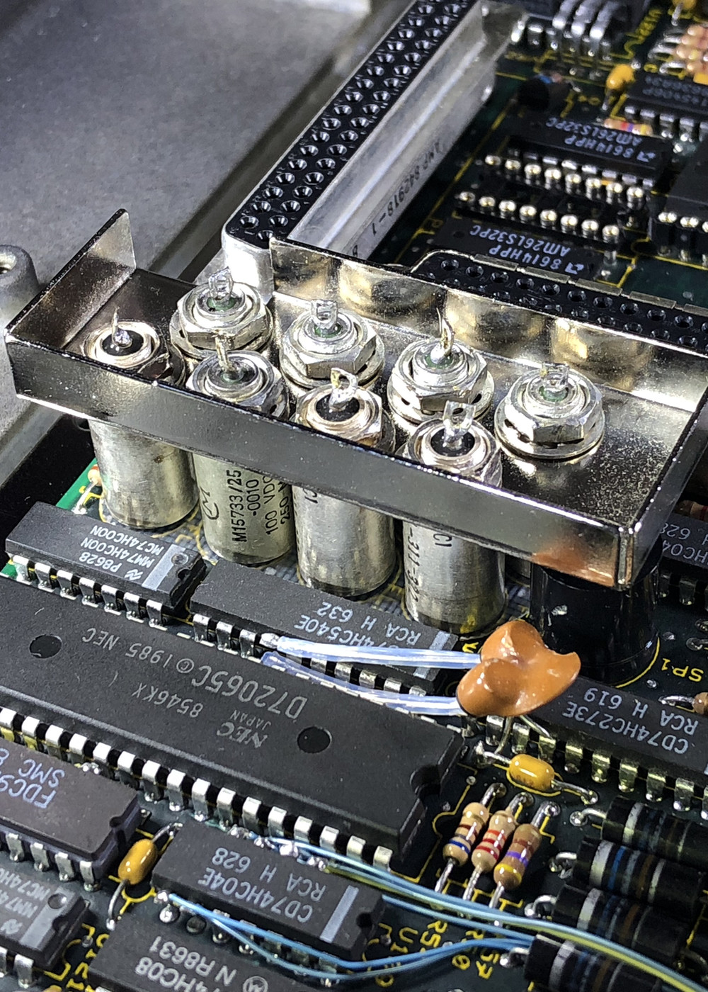
It's a phalanx of EMI filters, one for each DC line plus GND. Specifically, these are hermetically sealed case filters and the type of filter network they employ is called "Pi" or "𝝿", so named because of the circuit diagram's resemblance to the mathematical symbol.[2]
All the filters are soldered to the motherboard and threaded through a top plate which, in addition to connecting all the filters' cases, has a lip running across its edges where fingerstock is clipped. The whole thing is secured with each filter getting a lockwasher and hex nut.
As for what's going on in one of these filters, the manufacturer describes each as two discoidal capacitors with an inductor between them. A lead runs through this filter network and then each end is sealed with glass.
The capacitor elements shunt the interference to ground, and the series inductor elements raise the impedance of the line making the shunt capacitor elements even more effective.
There are two different models used in the TGC, one rated at 100V for the VCC, +5V, and GND rails, and another for the remaining +12V, +15V, -15V, +3.6V, and +5V.